Precast Boundary Wall Design
We design free-standing and load-bearing precast concrete boundary walls as a complete system — from the wind action on the panel face down to the soil bearing pressure under the footing. We work from your design criteria, geotechnical report and layout, or we develop the full structural design in-house, and we verify every element to the governing code at both ultimate and serviceability limit states.
The design checks we perform
Our boundary wall calculations treat each precast panel as a two-way element that must resist out-of-plane wind while also spanning horizontally between footings. We design every component in the load path:
- Wind load derivation
-
We calculate the design wind pressure on the free-standing wall and any parapet or solid-fence zones, including force coefficients, terrain and height factors, and net pressure across the panel, to ACI/ASCE or Eurocode EN 1991-1-4 as the project requires.
- Panel – wall action (out-of-plane)
-
We check the panel for out-of-plane flexure and shear under wind and any soil/retained loads, sizing vertical and horizontal reinforcement and verifying minimum steel and cover.
- Panel – beam action (spanning between footings)
-
Where panels span horizontally between columns or footings we design them for flexure, shear and torsion, and check deflection and crack width under service load.
- RC column / pilaster design
-
We design the supporting columns and planted columns for combined axial load and biaxial bending using P–M interaction, and detail ties and lap/anchorage lengths.
- Footing design
-
We verify the footing for flexure, one-way (beam) shear and two-way (punching) shear, check crack width, and confirm soil bearing pressure, sliding and overturning stability under wind and self-weight.
- Dowel-bar and pocket / socket connections
-
We design the panel-to-footing connection — whether by dowel bars or a pocket (socket) foundation — resolving the connection forces and checking grout, embedment, anchorage and bearing.
- Lifting and handling
-
We check the demoulding, lifting and erection stages, including insert capacity, dynamic factors and panel stresses during handling.
Loading cases we consider
We tailor the load combinations to the wall's exposure and use, including walls with and without vehicular traffic surcharge, gate and opening panels, elevation-specific wind zones, and the temporary lifting and erection stages. Each case is run at ultimate limit state for strength and at serviceability limit state for crack width and deflection.
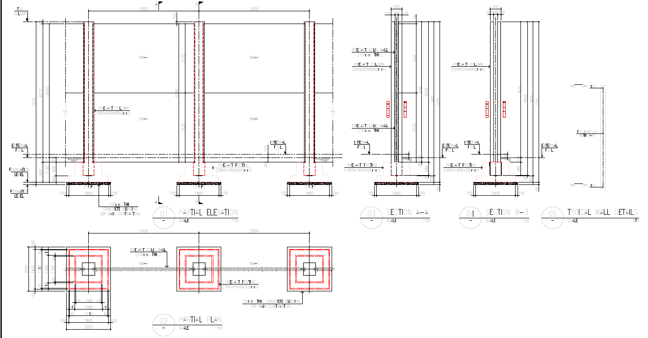
Typical General Arrangement and Details
Governing standards and how we apply them
- ACI 318-19
-
Our primary RC code for strength design and detailing — flexure, shear, punching, development and anchorage length, and serviceability. We apply the strength-reduction and load factors consistently across panel, column and footing.
- BS 8110
-
Used where a project is specified to British practice, including its serviceability crack-width approach for panels and footings.
- Eurocode (EN 1991-1-4 and EN 1992-1-1)
-
EN 1991-1-4 for wind on free-standing walls and parapets, and EN 1992-1-1 for RC design and crack-width control. Serviceability crack-width checks are carried out with EC2-compliant calculation methods.
- QCS
-
We align material properties, durability and cover with the project's general specification so the design is consistent with local approval requirements.
Why choose Precasterz for boundary wall design
- Whole-system verification
-
We design the panel, column, connection and footing as one load path, so nothing is checked in isolation and the connection forces are carried consistently into the foundation.
- Multi-code capability
-
We deliver to ACI 318-19, BS 8110 or Eurocode, matching whatever your consultant or authority has specified, with a clear, auditable calculation set.
- Buildable, economical detailing
-
Our reinforcement and connection details are optimised for casting, lifting and erection, reducing waste and avoiding site clashes.